Tuesday, 13 December 2011

Network Protocols

Transmission Control Protocol (TCP):
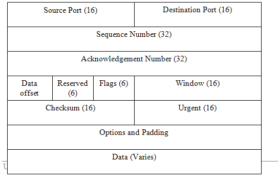
TCP is the transport layer of the protocol and serves to ensure a reliable, verifiable data exchanged between hosts on a network. TCP breaks data into pieces, wraps the pieces with the information needed to identify it as a piece of the original message, and allow the pieces to be reassembled at the receiving end of the communications link. The wrapped and bundled pieces are called Datagrams (or segments).


  • Source port and Destination port ensure that data is sent back and forth to the correct application process running on each machine.
  • Segment Number allows datagrams to be rebuilt in the correct order in the receiving device, and checksum allows the protocol to check whether the data sent is same as data received.
  • Acknowledgement number indicates that the data was received successfully, and Offset specifies the length of the header in 32-bit chunks.
  • Reserved specifies variables that are set aside for future use, it must contain ZEROS, and Flags , these are six one-bit fields that indicate various things, like whether segment is end of higher-layer message, acknowledgement number is significant, sender is requesting that a virtual circuit, data in the segment is urgent.
  • Window provides a way to increase the number of segments transmitted before the sender excepts an acknowledgement, and Urgent gives the location where the urgent data ends.
  • Options and Padding communicates various parameters of TCP virtual circuit, like maximum segment size, and it also ensures that the header ends on a 32-bit boundary so that the offset field makes sense as a whole number.
Internet protocol (IP) :
The network layer portion of the DoD model is called the Internet layer. The main protocol at this layer is the Internet Protocol (IP). IP is considered connectionless; i.e; it does not swap control information in order to establish an end to end connection before starting a transmission. This is known as best effort transmission. and if a packet is lost in transmission, IP must rely on TCP to determine it the data did not arrive successfully.


Address Resolution Protocol (ARP) :

The network layer protocol, ARP, associates the physical hardware address of a network node to its already known IP address. Using ARP, an IP process construct a table that maps ip addresses to mac addresses of nodes on LAN. When a node needs to send a packet to a known IP address on local sub-net, it first checks the ARP cache to see it the physical address information is already present. If so, that address is used and network traffic is reduced.


Internet Control Message Protocol (ICMP) :
It works at the network layer and provides the functions used for Network layer management and control. Routers send ICMP messages to respond to undeliverable datagrams by placing an ICMP message in an IP datagram and then sending the datagram back to the original source. The PING command.

ICMP EXAMPLE


User Datagram Protocol (UDP) :
It is a transport layer connectionless protocol that does not provide the reliability services with TCP but provides best effort transmission services to application protocols.It gives applications a direct interface with IP and the ability to address a specific application protocol running on a host via a port number without setting up an end-to-end connection.

TCP/IP Model

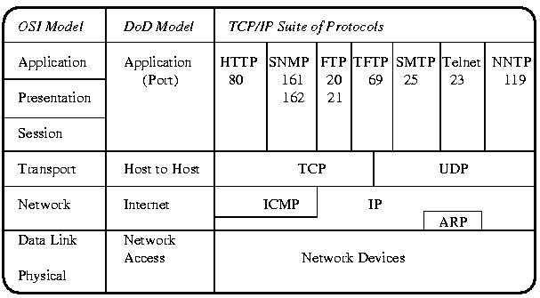
Because TCP/IP is so central to working with the Internet and intranets, you should understand it in details. TCP/IP uses the Department of Defense (DoD) model, which describes communications in only four layers.

DoD model:
In late 1960s, Advanced Research Projects Agency (ARPA) carried out a research project to connect a number different networks designed by different vendors into a network of networks (the "Internet"). And the model proposed for transmission of data was known as DoD model, it describes the communication in four layers: 
  • The Network Access Layer is responsible for delivering data over the particular hardware media in use. Different protocols are selected from this layer, depending on the type of physical network.
  • The Internet Layer is responsible for delivering data across a series of different physical networks that interconnect a source and destination machine. Routing protocols are most closely associated with this layer, as is the IP Protocol, the Internet's fundamental protocol. 
  • The Host-to-Host Layer handles connection rendezvous, flow control, retransmission of lost data, and other generic data flow management. The mutually exclusive TCP and UDP protocols are this layer's most important members.
  • The Process Layer contains protocols that implement user-level functions, such as mail delivery, file transfer and remote login.
TCP/IP was first proposed in 1973 and was split into separate protocols, TCP and IP, in 1978. In 1983, TCP/IP became the official transfer mechanism for all connections tp ARPAnet, replacing the earlier Network Control Protocol. We will study different protocols of TCP/IP model in details in later posts.

DoD model is theoretically comparable with OSI model :


IP Addresses and MAC Addresses

MAC Addresses
The MAC (or Hardware) address is used by devices to communicate on the local network. Hardware addressing is a function of the Data-link layer of the OSI model. MAC address that is usually hard-coded on the network card, this means The MAC address cannot be altered; the MAC address is often stored in flash on the NIC, and thus can be changed with special utilities.MAC address is represented in two formats (either notation is acceptable):
                                       00:43:AB:F2:32::13
                                       0043:ABF2:3213
           MAC address is a 48 bit hexadecimal coded address. first 24 bits tell the information about manufacturer and rest 24 bits represent the machine's information.
for example: 00:43:AB   stores manufacturer's details and F2:32:13 stores system's detail.

Changing MAC Address:
  1. open Network sharing center----> change adapter setting----> choose connection type (LAN or Wireless LAN)
  2. go to properties---> check connection controller (optional) ---> configure -----> Advance
  3. Now click on the Network Address, you will see that it is selected as "not present", select "value" and enter some value of MAC address.
  4. Your MAC address has been changed for a while. Once you turn off your machine the value will be set to default.
  5. to change value permanently, you will have to change value from "registry", it has been discouraged to change value from the registry if you don't have sound knowledge of registry, it may crash your system.                   
IP Address
IP Addressing is a function of the network layer of the OSI model. It helps in routing data packets hop by hop, node by node in the network. IP address is a 32 bit hexadecimal coded address. Few initial bits represent network id, and rest bit represent host address in the network.
for example:    ip address  192.168.65.133
                       sub-net mask: 255.255.255.0

so,   network address is 192.168.65.0
   and host location in the network is 133th position.

To Avoid wastage of logical addresses in the network sub-netting is done. To understand sub-netting, you will have to learn IP Addressing. Please watch videos shared below to understand IP addressing in detail. I recommend you to watch these videos, if you are interested in designing and managing networks.

IP Addressing Scheme:


IP Sub-netting And Addressing:


To view all network addresses of your machine:
  start--> run---> type "cmd" then enter-----> type command "ipconfig  /all".

Monday, 12 December 2011

Logical Topology

The Data Link layer also bars the responsibility of dictating the logical topology of a network, or the way the devices perceive the topology of the network. A logical topology differs from a physical topology in that the physical topology dictates the way the cables are laid out, whereas the logical topology dictates the way the information flows. The types of logical topologies are the same as the physical topologies except that the information flow specifies the type of logical topology in use.For example, in early days of Ethernet, networks were physically wired using a bus topology.Once twisted pair and fiber were introduced into the Ethernet Physical layer, hubs were designed to allow the network to be wired as a physical star while allowing the devices attached to the hub to continue to believe they were part of a bus, making this configuration a physical star/logical bus. Finally, the DLL can describe the method of media access.There are some media access methods, discussed below:

Contention: Every device "competes" with other devices for the opportunity to transmit, and each has an equal chance. If two devices transmit at the same time, a collision occurs and the devices try again.


Polling: A central device, called a controller, polls each devices in turn and asks if it has data to transmit. This type of media access virtually eliminates collisions.


Token Passing : This uses a special data packet called a token. When a device has the token, it can transmit. If it doesn't have the token, it can't transmit. This media access technology also eliminates collision problems.


Carrier Sense/Multiple Access with Collision Detection (CSMA/CD) : When a protocol that uses CSMA/CD has data to transmit, it first sense if a signal is already on the wire (a carrier), indicating that someone is transmitting currently. That's the "Carrier Sense" part. If no one is transmitting, it attempts a transmission. If someone else transmits at the exact same time, a collision occurs. Both senders "back off" and don't transmit until some random period of time has passed. That's the "Collision Detection" part. "Multiple Access" means that more than one station can be on the network at the same time.

Carrier Sense/Multiple Access with Collision Avoidance (CSMA/CA): It is identical to CAMA/CD, but instead of sending the whole data chunk and then listening to hear if it was transmitted, the sender transmits a request to send (RTS) packet and waits for a clear to send (CTS) before sending. When it receives the CTS, the sender sends the chunk.


Difference between CSMA/CD and CSMA/CA:
Say you want to cross a busy street and you want to use one of these protocols to cross it. If you are using CSMA/CD, you just cross the street. If you get hit, you go back to the curb and try again. If you're using CSMA/CA , you send your friend across. If he makes it, it's probably OK for you to go.

OSI Model


The OSI model was designed to promote interoperability by creating a guideline for network data transmission between computers and components that have different hardware vendors, software, operating system, and protocols.The OSI model consists of seven layers. Each Layers performs a specific function and then passes on the result to another layer.

Understanding Data Transfer using OSI model.

Application Layer: The highest layer; defines the manner in which applications interact with the network including databases, e-mail, and terminal-emulation programs using Application layer protocols similar to Lightweight Directory Access Protocol (LDAP), Simple Mail Transfer Protocol (SMTP), and telnet etc.
Presentation Layer: This layer is responsible for the formatting and code conversion of data being passed up to the Application layer.In this layer, character sets are converted (e.g., from ASCII to Unicode or EBCDIC) and data is encrypted. Data may also be compressed in this layer. Anything that is done to the data on the transmitting device must be undone on the receiving device. Presentation Layer is responsible for recognizing file types in an incoming data stream and performing any massaging to the dta to make a file presentable to the Application protocol.
Session Layer: It defines how two computers establish, synchronize, maintain and end a session. Its functions such as security authentication, connection ID establishment, data transfer, acknowledgements, and connection release take place here.
Transport Layer: It is responsible for checking that the data was delivered error-free. It is also used to divide a message that is too long into smaller segments and, in the reverse, take a series of short messages and combine them in to one longer segment.This layer also handles logical address/name resolution. Additionally, this layer can send an acknowledgement that it got the data packet.
Network Layer: It is responsible for logical addressing and translating logical addresses into physical addresses.A little-known function of the network layer is prioritizing data. Nobody is hurt it an e-mail message is delayed a fraction of a second but delaying audio or video data a fraction of a second could be disastrous to the message. This prioritization is known as quality of service (QoS). This layer controls congestion, routes data, build and tear down packets. Routers and manageable switches operates on this layer. Routing protocols (RIP, OSPF, EIGRP, BGP etc)are being implemented on this layer.


Data-Link Layer: It takes raw data from the physical layer and gives it a logical structure, known as a frame. in the opposite direction of flow, the Data Link layer hands frames down to the Physical layer for bit-level encoding onto the networking medium.Frames include information about where the data is meant to go, which device on the local link sent the data, and the overall validity of the bytes sent. It also controls functions of logical network topologies, physical addressing as well as data transmission synchronization and connections. Non-manageable switches and bridges operate at this layer.
Physical Layer: Physical layer is responsible for controlling the functional interface, such as transmission technique, encoding scheme, cable specifications, pin layout, and connector.
                 Physical layer concept involve a network component that is tangible or measurable. For example, when a protocol at the physical receives information from the upper layers, it translates all the data into signals that can be transmitted on a transmission medium.

Data Flow in a Network


Saturday, 10 December 2011

Networking Devices

Now that you are familiar with the various types of media and connections, you should learn about some devices commonly found on today's network.

NIC: 
NIC
The network interface card, as its name suggests, is the expansion card you install in your computer to connect, or interface, your computer to the network. This device provides the physical, electrical, and electronic connections to the network media. Generally all NICs have one ot two light emitting diodes (LEDs) that help in diagnosing problems with their functionality.


HUB:
A hub is a devices that connects all segments of the network together.Every device in the network connects to the hub through the single cable. Any transmission received on one port will be sent out all the other portsin the hub, including the receiving pair for the transmitting device. A broadcast sent out by any device on the hub will be propagated to all devices connected to hub. Any two or more devices connected to hub have capability of causing collision with each other. The LED will turn orange from green on collision, and we will have to turn off the hub, and wait for a while, then restart the hub, now the hub will be work properly. This was the major drawback of hubs.

SWITCH:
Like a hub, a switch connects multiple segments of the network together, with one important difference. Whereas a hub broadcast anything it receives, a switch recognizes frame boundaries and pays attention to the MAC address of the incoming frame as well as the port on which it was received. A switch, when it is installed in the network, first time it broadcasts to store MAC address of the devices in the network in its table, whenever it receives a data packet then it matches MAC address from its MAC table and forward it to specific port. In this way, probability of collision is being reduced. There are two types of switches:
  • Manageable: operates on Data Link Layer and Network Layer, it may be used to implement routing protocols in a small network.
  • Non-manageable: operates on Data Link layer. It has MAC table, it does not support routing protocols.
switching methods:
  • Cut-through Method: cut-through switching is a method for packet switching systems, wherein the switch starts forwarding a frame (or packet) before the whole frame has been received, normally as soon as the destination address is processed. This technique reduces latency through the switch, but decreases reliability.
  • Store & Forward Method: information is sent to an intermediate station where it is kept and sent at a later time to the final destination or to another intermediate station. The intermediate station, or node in a networking context, verifies the integrity of the message before forwarding it.
BRIDGE:
A bridge, specifically a transparent bridge,is a network device that connects two similar network segments together. The primary function of a bridge is to keep traffic separated on both sides of the bridge. Bridge is used in bus topology. for example :


MSMQCLIENT1 wants to send data to MSMQCLIENT5, bus will broadcast the data in upper segment and try to broadcast in lower segment also, since MSMQCLIENT5 is in upper segment so it will be wastage of resource utilization by broadcasting data in lower segment. hence we use bridge, it will match MAC address of the data packet header with its MAC table, since MSMQCLIENT5 is not in lower segment so it will not allow data flow in lower segment.


ROUTER
Representation of a router
A router is a network device that connects multiple, often dissimilar, network segments into an internetwork. The router, once connected, can make intelligent decisions about how best to get network data to its destination based on network performance data that it gathers from the network itself. Router operates at Network layer. It decide the best route with the help of network layer address. We will study about router and routing protocols in detail later on. Router Vendors:
Cisco, Juniper, ZDNet etc


GATEWAY
A gateway is any hardware and software combination that connects dissimilar network environments. Gateways are the most complex of network devices because they perform translations at multiple layers of the OSI model. For example, a gateway is the device that connects a LAN environment to a mainframe environment. E-mail gateway translates LAN based mail messages into the SMTP format that Internet mail uses.

MODEM
A modem is a device that modulates digital data onto an analog carrier for transmission over an analog medium and then demodulates from the analog carrier to a digital signal again at the receiving end.


FIREWALLS
Its job is to protect LAN resources from attackers on the Internet. Similarly, it can prevent computers on the network from accessing various services on the Internet. It can be used to filter packets based on rules that the network administrator sets. Firewalls can be stand-alone "black boxes", or can be set up in software on a server or router.

Friday, 9 December 2011

Physical Media

Although it is possible to use several forms of wireless networking, such as radio frequency and infrared, the majority of installed LANs today communicate via some sort of cable.In following section, we'll look at three types of cables:
  • Coaxial
  • Twisted Pair
  • Fiber Optic
Coaxial Cable:
Coaxial cable contains a center conductor, made of copper, surrounded by a plastic jacket, with a braided shield over the jacket.A plastic such as polyvinyl chloride (PVC) or fluoroethylenepropylene (FEP) covers this metal shield. The Teflon type covering is frequently referred to as a plenum-rated coating. That simply means that the coating doesn't begin burning until a much higher temperature, doesn't release as many toxic fumes as PVC when it does burn, and is rated for use in plenums that carry breathable air, usually as nonenclosed fresh-air return pathways that share space with cabling.


types of coaxial cables are: (RG= radio guide)

RG8 :
  • segment length is 500 m.
  • Interference is good compared to any copper cable.
  • resistance 50 ohm.
  • BNC-T or Vampire Tap connector is used to connect this cable.
  • Used in 10base5 network
RG6:
  • broadband quad-shield cable that offers an impedance of 75 ohm.
  • lower attenuation
  • Used in cable TV, CCTV, satellite dish antenna.
RG59:
  • Better breakdown characteristics allows for high voltage use in scientific experiments.
  • Characteristic impedance 75 ohm.
  • Used in security camera, cable TV, home theater.
using Thin Ethernet: Thin Ethernet, also referred to as Thinet or 10base-2, is a thin coaxial cable.It is basically the sane as thick coaxial cable except that the diameter of the cable is smaller ( about 1/4" in diameter). Thin Ethernet coaxial cable is RG-58. With Thinnet cable, we use BNC ( BayoNet Connector or British Navel Connector) to attach stations to the network.

 
Twisted -Pair Cable:
Twisted-pair cable consists of multiple, individually insulated wires that are twisted together in pairs. Sometimes a metallic shield is placed around the twisted pairs. hence, the name shield twisted-pair (STP). More commonly, you see cable without outer shielding; it's called unshielded twisted-pair (UTP). UTP is commonly used in twisted-pair Ethernet ( 10Base-T, 10Base-TX, etc), star-wired networks. Let's take a look at why the wires in this cable type are twisted. When electromagnetic signals are conducted on copper wires that are in close proximity, some electromagnetic interference occurs. This interference is called crosstalk. Twisting two wires together as a pair minimizes such interference and also provides some protection against interference from outside sources.
 
UTP cables:
  • Category 1: two twisted wire pairs. Voice grade (not rated for data communications).Oldest UTP, used in PSTN (Public Switched Telephone Network) .
  • Category 2: Four twisted wire pairs. Suitable for up to 4 Mbps, with a frequency limitation of 10 MHz
  • Category 3: Four twisted wire pairs with three twists per foot.Acceptable for transmissions up to 16 MHz.
  • Category 4: Four twisted wire pairs and rated for 20MHz.
  • Category 5: Four Twisted wire pairs and rated for 100MHz
  • Category 5e: Four Twisted wire pairs and rated for 100MHz, but capable of handling the disturbance on each pair caused by transmitting on all four pairs at the same time.
  • Category 6: Four twisted wire pairs and rated for 250MHz.

Fiber-Optic Cable :
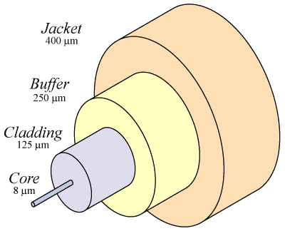
A fiber optic cable consists of a bundle of glass threads, each of which is capable of transmitting messages modulated onto light waves.Electrical signals are converted into light signals. TIR (Total Internal Reflection) phenomena is responsible for transmission of data. Because fiber optic cable transmits digital signals using light impulses rather than electricity, it is immune to Electromagnetic Interference (EMI) and Radio Frequency interference (RFI).
 
          The cable itself comes in two different styles: single-mode fiber (SMF) and multi-mode fiber (MMF). The difference between single-mode fibers and multi-mode fiber is in the number of light rays ( and thus the number of signals) they can carry. Multi-mode fiber is used for short distance application and single-mode fibers for longer distance.

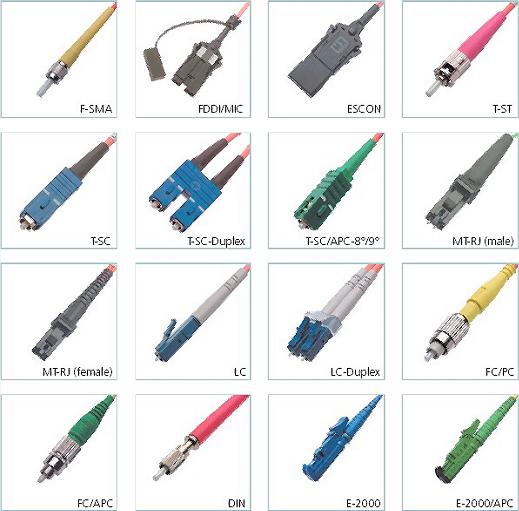
Fiber-optic connectors: 
 
  • Straight tip (ST) : joins individual fibers to optical device.
  • Subscriber Connector (SC) : attaches two fibers to send and receive signal.
  • Medium interface connector (MIC) : joins fibers to FDDI
  • Sub Miniature Type A (SMA) : uses individual connectors for each fiber stand.
 
NOTE:      mBase-n
  •  m indicates transmission speed in megabits
  • n can have different meaning. for example n=5, means 500m segment length but for n=2, segment length is 185m. Only the IEEE committee knows for sure what this was about.
for examples:
  • 10BASE-5 (Thickwire coaxial cable with a maximum segment length of 500 meters)
  • 10BASE-F (optical fiber cable)
  • 10BASE-T (ordinary telephone twisted pair wire)
  • 10BASE-36 (broadband multi-channel coaxial cable with a maximum segment length of 3,600 meters)